Voltage drop and power loss calculation in distribution system
The problem of voltage stability and voltage collapse has been studied and investigated for some decades now. Inside the power grid collapse and measures for preventing voltage instability and loss.
Distribution System Voltage Drop And Power Loss Calculation
For the voltage drop the NEC requires two calculations.
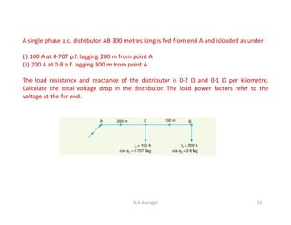
. One requiring a max drop of 15 during motor starting conditions and another during running conditions requiring 5 at 115 of FLA. This system is larger than those of many rural electric cooperatives that would have been covered by the proposal. Here voltage drop for 70 Sqmm Cable 58 is higher than define voltage drop 5 so either select higher size of cable or increase no of cable runs.
Based on the requirements of the specific electric power distribution system SIMARIS design safely and reliably dimensions a system solution from a broad product portfolio which is in compliance with all the relevant standards VDE IEC and reflects the present state of the art in technology. We refer to this as the voltage across the bulb or as the bulbs voltage drop. The basic voltage drop equation is below.
This is the first loss we have to deal with but of course theres nothing we can do about it. Voltage and it needs to surpass a certain level of contrary pressure caused by the wire. Dc power flow P dc depends on voltage differences at the sending and receiving ends as shown by.
Electrical parameter measurement function voltage current active power energy frequency power factor 2. Among leading power distribution companies Mangan Power offers a DC Voltage Drop Calculator to calculate the voltage drop as per the IEEE standard. Hardy CEng FIET in Transmission and Distribution Electrical Engineering Fourth Edition 2012.
Key points on how to design a fault-tolerant and reliable facility distribution system. FAULT LEVEL CALCULATION Dinesh Kumar Sarda 2. The rating in watts is equal to the rating in volts-amperes multiplied by the power factor.
The measurement is made with a capacitance bridge measuring the capacitance between windings and between windings and ground together with the power factor or loss angle of this capacitance. Reactive volt-ampere generated by the line charging volt-amperes of the lines. Power alarm threshold preset function can set power alarm threshold.
So from NEC Table 31015B16 a THWN 3 AWG copper cable is sufficient until we look at voltage drop. The voltage at the line terminals of a fire pump cant drop more than 15 of the rated voltage when the motor starts. Bayliss CEng FIET BJ.
For example one generating facility for a large steel plant in Sparrows Point Maryland has a generating capacity of 140 megawatts with a generating voltage of 13 kilovolts and with distribution voltages of 345 and 69 kilovolts. This is according to NEC 6957. UPS output power rating in watts UPS output in volts-amperes power factor.
The inefficiency is built in. Using network topology transmission line parameters transformer parameters generator location and limits and load location and compensation the load-flow calculation. If we select 2 runs than voltage drop is 28 which is within limit 5 but to use 2 runs of cable of 70 Sqmm cable is not economical so its necessary to use next higher size of cable.
This is not the case on a dc line. Overload alarm function over power alarm threshold backlight and power flashing to alarm. The goal of a power flow study is to obtain complete voltage angle and magnitude information for each bus in a power system for specified load and generator real power and voltage conditions.
These assumptions will set the stage for each single-phase voltage drop calculation. UPS power ratings are quoted in volt-amperes VA andor watts. The load-flow calculation is the most common network analysis tool for examining the undisturbed and disturbed network within the scope of operational and strategic planning.
Once this information is known real and reactive power flow on each branch as well as generator reactive power output can be analytically determined. Fault level at any given point of the Electric Power Supply Network is the maximum current that would flow in case of a short circuit fault at that point. Overall solar system losses including power loss in solar panels account for approximately 26 of the power generated so whatever we can do to improve.
Power will flow over an ac line even if voltages at the sending and receiving ends have the same magnitude provided that the phase angles of the voltages at each end are different. In low-voltage networks domestic appliances are. Lets start with a simple example.
In fact this is a good way to characterize PV system losses those we can improve and those we cannot. A power factor value of 10 or less for distribution transformers is generally used as an acceptable value. In an embedded system a 12V bus rail is available from the front-end power supply.
For a three phase line the charging current phase. Voltage fluctuations are described by the IEC as cyclical variations of the voltage envelope or a series of random voltage changes of up to 10 of the nominal. The simplest approach to generate the 33V is to use a resistor divider from the 12V bus as shown in Figure 1.
The circuit breaker should be capable of Breaking Making current as per their ratings should also have Rated short time capacity. Call 310-835-8080 to know more. Voltmeters are used to measure the voltage across the light bulbs.
Fault Level Calculation 1. Where V n voltage to neutral in volts phase voltages in volts C n capacitance to neutral in farads. On the system board a 33V voltage is needed to power an operational amplifier op amp.
When current is flowing through the light bulb the resistance of the filament causes a loss of voltage that is proportional to the resistance and the amount of current. V line voltage in volts. The energy can be reset use the key.
The battery load for sizing purpose is the UPS output rating in watts divided by the efficiency of the inverter. Approximate voltage drop calculation for motor starting To get started lets take a quick look at fire pumps. Does it work well.
Store data when power. Suitable components are selected automatically. A voltage drop then is the amount of voltage loss that the contrary.
Also reactive volt-ampere generated by the line charging volt-amperes of the lines. Nowadays power system reliability is more important.
Distribution System Voltage Drop And Power Loss Calculation

Power Flow In Mv Radial Network And Calculation Of Voltage Drop And Loss

Calculate The Distribution Line Power Loss With Distance And Solve It To Get An Optimum Distance

Voltage Drop Formula Example Calculation Electrical4u

Distribution System Voltage Drop And Power Loss Calculation
Distribution System Voltage Drop And Power Loss Calculation

Voltage Drop Calculation Methods With Examples Explained In Details Eep
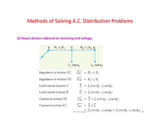
Distribution System Voltage Drop And Power Loss Calculation
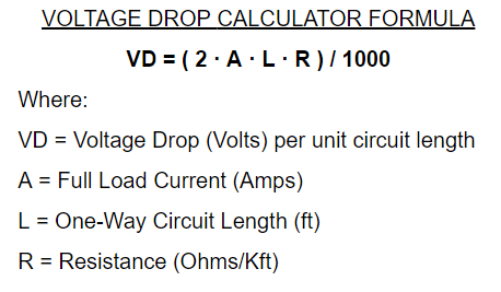
Permissible Voltage Drop Energypedia

Voltage Drop Calculation Methods With Examples Explained In Details Eep
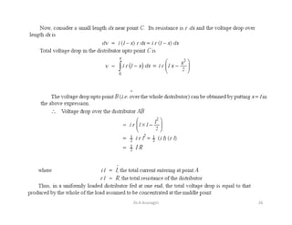
Distribution System Voltage Drop And Power Loss Calculation

Distribution System Voltage Drop And Power Loss Calculation

Voltage Drop Formula Example Calculation Electrical4u

Distribution System Voltage Drop And Power Loss Calculation
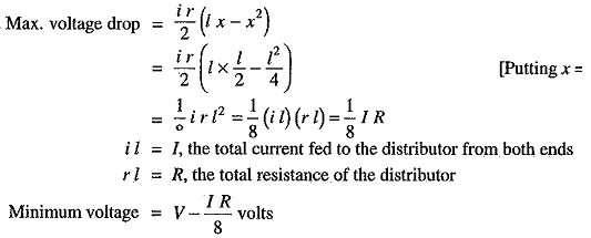
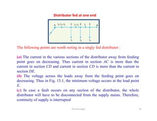
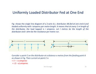
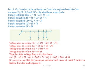
Dc Distribution Calculation Dc Distributor Fed At One End

Calculate The Distribution Line Power Loss With Distance And Solve It To Get An Optimum Distance
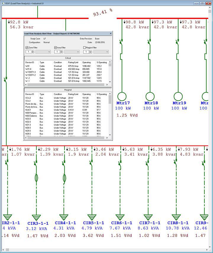
Load Flow Voltage Drop Analysis Software Powerflow Software Etap